Designing Trusses Step-by-Step
Step 1: Model dividers, rooftops, roofs, floors and primary pillars
Trusses are upheld by different items in building model and nature should be finished before trusses are included. All articles are not functioning as bearing segments. Dividers, shafts, rooftops, roofs and floors can function as bearing parts with some impediment.
- Bearing quality on dividers is determined.
- Pillar usefulness is set to Main shaft, bars ought to be upheld by vertical bearing component, which means section or bearing divider.
- Capacity property of the profiles which are moving loads from covering material like sheeting to trusses must be "Rafters" or "Joists".
- Profiles conveying loads from different members must be "Hip Rafters", "Valley Rafters" or "Ridge Beams".
- Physical contact or joint between members is expected to distinguish uphold relations and complete load move.
- "Rafters" ought to be upheld by divider and hip rafter. No resilience is permitted between end divider top and rafter.
- Change building divider tallness or hip incline stature if necessary.
- Try not to include free dividers into model, in light of the fact that outside of building they influence into fathoming of building measurements for wind load age.
- Utilize outside dividers just for building envelope not for inside dividers, outside divider chain ought to be shut that framework can perceive working inside zone for wind age.
Step 2: Generate truss territories and trusses
Truss territories are created by objects which are restricting the truss volume.
- Stature position of restricting articles, particularly a hip slant should meet cozy an end divider.
- Associations between trusses, jack trusses opposite to brace truss should meet support.
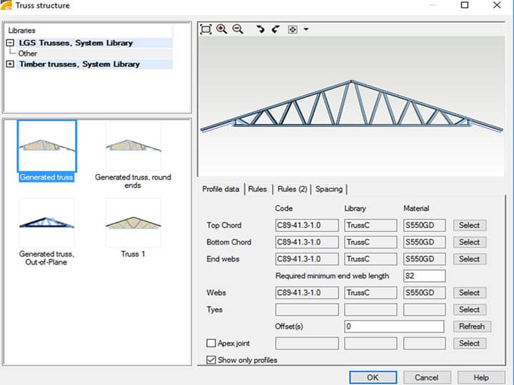
Step 3: Generate truss members
Truss members are created utilizing rules characterized by client.
- Check member boundaries and truss type.
- Check member material, chosen grade is utilized in engineering.
Step 4: Check associations between members
Associations must be characterized between truss members. Truss member surrounding is including associations between members yet physically embedded members must be checked by client.
- Check utilized clasp types and codes, limit of association depends on latch type and code.
- Cutting association just between truss members can be utilized yet then association isn't built.
- In the event that program is arranged to constrain web association at bearing area, at that point saddle truss verticals ought to be in accordance with top harmony of truss beneath or possibly center of red clasp design large scale in association ought to be between top harmony faces underneath.
- Use joist holders or direct screw association between trusses to produce uphold connection between brace truss and trusses upheld by support.
Step 5: Check upholds
There must be physical contact or association among upheld and supporting articles. Trusses which are upheld by other trusses should be associated by client.
- Check truss to truss supports and include associations
- Check bearing divider statures and contacts with truss members
- Check bearing fundamental pillar positions and contacts with truss members
- Hip drop truss/brace slanting top harmonies ought not stretch out inside hip rafter, in any case awful help connection is found during engineering
Step 6: Generate truss names and drawings
Truss and truss member names are made with truss drawing. Truss drawing must be made and refreshed before Truss Design. Names are utilized to allude to engineering results.
- Make truss drawings before Truss Design.
- Update truss drawings if truss calculation is changed.
Step 7: Generate inside weight territory
Inner weight region is space inside structure restricted by outside dividers and inside roof or rooftop. In the event that roof is penetrable, at that point rooftop is restricting interior weight zone.
- Check created shut poly line to restrict inner weight zones and modify poly line if necessary.
Step 8: Generate wind loads for roof and rooftops
Wind loads are produced by the chose construction standard.
- Select primary breeze bearing during input dependent on building site geography and ecological angles.
- Check Design Criteria defaults, particularly fabricating area contrasted with territory geography.
- Check importance of presentation and nook boundaries from construction regulation
Step 9: Add other line, point and zone loads
Point, line or zone loads can be displayed physically. All loads ought to be demonstrated into same drawing-model pair where bearing item is. To apply point or line load to base harmony, apply load first to roof and afterward move it to contact with base harmony.
- Watch that point and line loads are applied to truss members not to trusses
Step 10: Run engineering
Engineering should be possible for one or numerous trusses or rafters. Passed truss in the wake of engineering is shown in green shading mark. Engineering name is included into end of truss mark.
- Check create mistakes and admonitions; they manage you to make changes into your structure model.
- Association model checker can be utilized to advise missing help relations.
Step 11: Check engineering results
Results can be opened in 3d model or 2d drawing. Drawing shows pressure lists for every member. In the event that the pressure list is over 1.0, at that point limit of member is surpassed.
What to do if the design doesn’t work?
- Reduce truss dispersing
- Increment the quantity of the askew members
- Utilize boxed truss structures for the basic parts
- Use employed trusses
- Check load way
Step 12: Create engineering printouts
Engineering results are appeared in printouts.
- Watch that introduced underpins are in right areas.
- Check second and hub power graphs.