The Construction Feeds
Home Editor's Desk - Editorials Comparative Analysis of Slab to Beam Load Transfer

Comparative Analysis of Slab to Beam Load Transfer

Load transfer mechanism in reinforced cement concrete (RCC) structures are a truly intriguing matter. The loads of a floor fall totally on the floor slab. They are transferred to the beams, then to the columns, and finally to foundation. Today, we will do a comparative analysis of slab to beam load transfer.

The forces acting on a slab are expressed as slab pressure loads, which are told in terms of kN/m2. However, when these loads are transferred to the beams supporting the slab, they morph into what we call line loads on beams, given in kN/m. This transfer has to be uniform on all sides (unless you have designed it specially for skewed loads) or else the flooring may crack, or worse.

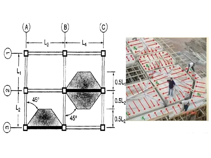
Reynolds and Steedman (2005) present some very useful formulas to represent uniformly distributed slab loads transferred to beams. These formulae are great for analyzing the load transfer system from a two-way or one-way slab to its supporting beam.

The formulas are as follows:

  • One-way slab (ly/lx > 2)
    • Long span: p = nlx/2
    • Short span: p = nlx/5
  • Two-way slab (ly/lx < 2)
    • Long span: p = nlx/2(1 ? 1/3k2)
    • Short span: p = nlx/3
  • Where,
    • n = load from slab
    • ly = length of long side of the slab
    • lx = length of short side pf the slab
    • k = aspect ratio = ly/lx

We can take three different approaches to do a comparative analysis of slab to beam load transfer. These are:

  • Finite element analysis using Staad Pro
  • Yield line method using Staad Pro
  • Manual calculation using formulas

Now let us look at each method one by one, each once for a one-way slab and a two way slab.

One-way slab
Data given:

  • Slab dimension: 2.5 m x 7 m
  • Supported by beams on all 4 sides
  • Pressure load = 10 kN/m2

Therefore,
Aspect ratio, k

  • = ly/lx
  • = 7/2.5
  • = 2.8

1. Calculation using finite element analysis using Staad Pro

Long span beam

  • Maximum span moment = 60.689 kNm
  • Support moment = -6.337 kNm
  • End shear = 29.7 kN

Short span beam:

  • Maximum span moment = 12.091 kNm
  • Support moment = +2.81 kNm
  • End shear = 11.6 kN

2. Yield line method using Staad Pro

Long span beam:

  • Maximum span moment = 63.4 kNm
  • Support moment = -9.9 kNm
  • End shear = 35.9 kN

Short span beam:

  • Maximum span moment = 6.16 kNm
  • Support moment = -0.346 kNm
  • End shear = 7.81 kN

3. Manual analysis using formulae

Load on long span beam

    • = nlx/2
    • = (10 x 2.5)/2
    • = 12.5 kN/m
  • Maximum span moment
    • = ql2/8
    • = (12.5 x 72)/8
    • = 76.56 kNm
  • End shear
    • = ql/2
    • = (12.5 x 7)/2
    • = 43.75 kN

Load on the short span beam

    • = nlx/5
    • = (10 x 2.5)/5
    • = 5 kN/m
  • Maximum span moment
    • = ql2/8
    • = (5 x 2.52)/8
    • = 3.906 kNm
  • End shear
    • = ql/2
    • = (5 x 2.5)/2
    • = 6.25 kN

So, we can see that in the one-way slab system, in the longer side, the finite element analysis and yield line analysis methods give quite similar results. But our manual calculation has overestimated the bending moment and shear forces.

In the short span direction, both the yield line method and manual method underestimates the loads transferred. However, the manual calculation gives quite good results for bending moments that can be used for design.

Two-way slab
Data given:

  • Slab dimension: 5 m x 6 m
  • Supported by beams on all 4 sides
  • Pressure load = 10 kN/m2

Therefore,
Aspect ratio, k

  • = ly/lx
  • = 6/5
  • = 1.2

1. Calculation using finite element analysis using Staad Pro

Long span beam

  • Maximum span moment = 73.063 kNm
  • Support moment = -2.71 kNm
  • End shear = 37.6 kN

Short span beam:

  • Maximum span moment = 54.495 kNm
  • Support moment = -0.814 kNm
  • End shear = 31.9 kN

2. Yield line method using Staad Pro

Long span beam:

  • Maximum span moment = 76.562 kNm
  • Support moment = -9.897 kNm
  • End shear = 39.4 kN

Short span beam:

  • Maximum span moment = 46.987 kNm
  • Support moment = -5.096kNm
  • End shear = 30.151 kN

3. Manual analysis using formulae

Load on long span beam

    • = nlx/2(1 ? 1/3k2)
    • = [(10 x 5)/2] x [1 ? 1/(3 x 1.22)]
    • = 19.212 kN/m
  • Maximum span moment
    • = ql2/8
    • = (19.212 x 62)/8
    • = 86.454 kNm
  • End shear
    • = ql/2
    • = (19.212 x 6)/2
    • = 57.636 kN

Load on the short span beam

    • = nlx/3
    • = (10 x 5)/3
    • = 16.667 kN/m
  • Maximum span moment
    • = ql2/8
    • = (16.667 x 52)/8
    • = 52.084 kNm
  • End shear
    • = ql/2
    • = (16.667 x 5)/2
    • = 41.6675 kN

Now, in the case of two-way slabs, our observations are obviously not much different. The bending moment and shear forces are quite similar in automated Staad Pro methods (1 and 2). Again, manual analysis overestimates the slab loads transferred to the beam in the long span.

Whereas in the short span, yield line method falls short of expectation but manual method gave came very close to the automated finite element analysis. This is a dependable result and thus can be used in design. However, the sagging moment in the long span needs to be redistributed by 10%.

Comparative Analysis of Slab to Beam Load Transfer